laser spot positioning and spot quality diagnosis and verification case
This case records the offline algorithm verification of laser spot positioning, beam profile analysis and quality diagnosis. The input uses analytically synthesized light spots with known pixel true values and controlled geometric data, which are used for verification center estimation, candidate extraction, anomaly diagnosis and statistical calculations, and are not part of the customer's on-site or actual machine performance acceptance.

Project Judgment Summary
Analytical composite graph example
The following images are used to show the input differences covered by this offline verification. They are all analytical composite images, not actual camera shots, customer samples or production line inspection results.
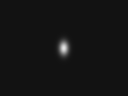
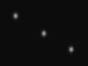
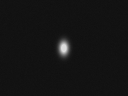

Verification tasks
Light spot center calculation requires simultaneous processing of background, morphology, and effectiveness. Only returning one coordinate cannot indicate whether the image is saturated, whether the light spot falls on the ROI boundary, and it cannot distinguish between valid measurements and invalid observations.
This verification separately checks single-point center positioning, multi-point candidate extraction, primary and secondary axes and surrounding energy diameters, saturation and truncation diagnosis, as well as two-dimensional mapping, line of sight conversion and repeatability statistics. Each item uses corresponding inputs and criteria, and one positioning error is not used to replace all system indicators.
Samples and verification conditions
The image is generated by the analytical spot model, including background, amplitude, elliptical shape, fixed gradient or specified noise; coordinates and parameters are recorded with the sample. The image adopts 8-bit grayscale format, with 6 groups of resolutions of 128×96 pixels and boundary truncated samples of 64×64 pixels.
| Image input | Check content |
|---|---|
| Single point and circular light spot | Center positioning and surround energy calculation |
| Light spot with background gradient and noise | Center estimation under conditional perturbation |
| Saturation and boundary cutoff spots | Exception status and availability check |
| multiple separated spots | Number of candidates, centers and one-to-one matching |
| Rotating elliptical light spot | Second-order moment primary and secondary axes and directions |
There are 7 groups of image inputs in total. 2D mapping, camera line of sight, and repeatability also use controlled geometry or coordinate input, which is not mistaken for real camera acquisition.
| record item | Conditions |
|---|---|
| Verification date | October 24, 2026 |
| computing environment | Python 3.11.9、NumPy 2.4.6、OpenCV 4.13.0 |
| truth source | Analyze spot parameters, known mapping and controlled coordinates |
| Result usage | Algorithm numerical regression and abnormal behavior verification |
Treatment method
First check the image, ROI and background, and then perform light point extraction and center estimation according to the task; the results of morphological calculation and quality inspection are retained respectively. When coordinate mapping is required, use the corresponding two-dimensional calibration input; repeatability statistics only process repeated coordinates under specified conditions.
Adaptive threshold and grayscale centroid calculation are used for a single light spot; connected domain candidate extraction is first performed for multiple separated light spots; images that are saturated or touching the ROI boundary are individually checked for status. Point matching, calibration mapping and uncertainty propagation are verified separately to avoid masking upstream anomalies with downstream smoothing.
Verification results
12 benchmarks in the special record were passed. The following table excerpts some results. Each row corresponds to a different verification input and is not used for method ranking or device accuracy comparison.
| Verification items | Recording under synthetic or controlled input | Applicable explanation |
|---|---|---|
| Grayscale centroid single point positioning | Center error 0.0402 px | Pixel coordinate error of single point composite image |
| Multiple point candidate extraction | 3 candidates were detected, with a maximum center error of 0.0534 px | Three synthetic light spots that do not touch each other |
| Saturation and boundary truncation checks | Both structural anomalies were detected | Does not represent the detection rate of all real anomalies |
| 2D repeatability statistics | Radial RMS for 5 controlled coordinates is 0.1581 px | Statistical calculation results, not device repeated positioning indicators |
The center error is calculated as the Euclidean distance between the estimated center and the known pixel true value. px is a unit of pixels; the values in the table are rounded and cannot be directly converted to millimeter error or actual optical resolution.
Conclusion and scope of application
Records support numerical verification of this implementation on listed synthetic inputs and controlled geometry data, and can be used for regression testing prior to subsequent device adaptation. Actual speckle, exposure nonlinearity, stray reflections, motion blur, dead pixels, and actual calibration errors of the target device are not covered by these synthetic samples.
When deploying to specific equipment, original frames, exposure and lens configurations, actual calibration, independent physical truth values, and product domain reserved samples should be supplemented, and then errors, invalid frames, processing time, result update rate, and the operation of the agreed time should be verified respectively. This case does not provide conclusions on real-machine accuracy, frame rate or long-term stability that have not been tested above.
Project access reference
This verification path records calculation modules, samples, parameters and criteria separately to facilitate review after modifying the algorithm or replacing the input link. On this basis, the project can continue to adapt to acquisition and playback, coordinate definition, quality status, calibration files and result interfaces. The actual delivery scope is confirmed according to the equipment task.
Corresponding products:Laser spot positioning and beam profile analysis algorithm. When it is necessary to evaluate the installation adjustment, position deviation or beam profile analysis tasks, both normal and abnormal samples should be provided, as well as the units and allowable errors of the expected output.
FAQ
Can these data be used as positioning accuracy when purchasing equipment?
No. They are computational records at listed synthetic inputs and controlled coordinates, and device accuracy requires real imaging, real calibration and independent physical truth.
After the synthetic sample passes, is it still necessary to test the real image?
Needed. Synthetic samples are convenient for verifying numerical calculations, but they do not completely cover the actual optical path, sensor, target material, and environmental changes.
Is this case a customer production line delivery case?
No. This case is an offline algorithm verification and does not involve customer site, batch deployment or production line acceptance.
record source
Based on the "laser spot Calculation Algorithm Expansion and Verification" on October 24, 2026, the same batch of special benchmarks and synthetic map list. This information is an internal algorithm verification record and is not a third-party certification or complete standard measurement report.
Enterprise project promotion and acceptance
- scope confirmationClarify the objects, workstations, inputs, outputs, units, interfaces and abnormal conditions that must be covered.
- Sample verificationUse representative normal and abnormal samples to establish a baseline and record what works, what fails, and data gaps.
- Development joint debuggingComplete the algorithm, calibration, interface and equipment adaptation according to the approved scope, and retain the version, parameters and abnormal status.
- Item acceptanceUse independent samples and reference value retests to confirm errors, detection, tempo, stability and deliverables respectively.
Define the Development Scope with Samples and Device Requirements
laser spot positioning and spot quality diagnosis and verification case
Please describe the task object, original picture or video, target indicators, device platform, interface and sample situation.
Phone: 13910119357xuzhiyang0928@gmail.com